Formulating Plastics for Direct Laser Marking
By Scott Sabreen
The Sabreen Group, Inc.
Advancements in material science formulations, combined with nanosecond fiber laser technology, achieve unprecedented marking quality, contrast and speed on plastics that have been difficult, if not impossible, to laser mark. Many laser-enhancing additives are formulated to maximize laser light absorption at wavelengths operating between 1060-1070 nanometers, thus enabling compatibility with near-infrared laser sources.
What is the laser marking reaction mechanism?
A common surface reaction mechanism is "thermal chemical," whereby the energy absorbed in the substrate raises the local temperature of the material surrounding the absorption site high enough to cause thermal degradation of the polymer. Laser additives improve the degree of contrast, which can be further intensified by changing the laser set-up parameters. Polymers possess inherent characteristics to yield "dark-colored" or "light-colored" marking contrast. Each polymer-colorant grade, even within the same polymeric family, can produce different results. Colorant compounds that contain low amounts of TiO2, carbon black and mixed metal oxides also absorb laser light and, in some instances, improve the marking contrast.
How can laser-enhancing additives be assessed?
Commercially available laser additives are supplied in granulate and powder forms. Granulate products can be blended directly with the polymer resin, while powder forms are converted to masterbatch. These additives contain mixtures of antimony-doped tin oxide and/or antimony trioxide that impart a "grayish" tint to the natural (uncolored) substrate opacity. Color adjustments are made using pigments and dyes to achieve the final colormatch appearance. Based upon the specific additive and polymer, the loading concentration level by weight can range from 0.01 percent to 4.0 percent. Both granulate and powder form can be supplied as precompounded color material or color concentrate.
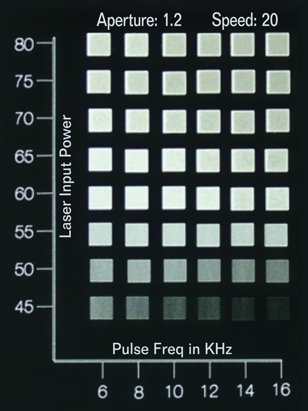
The "matrix grid array" is a basic evaluation method to assess laser additives/colorant formulations and laser performance on sample test chips. See photo.
The matrix grid array has preset marking process parameters, typically plotting percent laser power versus pulse repetition rate. For this example, marking speed and vector line fill are constant. The best quality "white" contrast mark, circled in yellow, occurs at 60 percent laser power and 10kHz pulse frequency repetition. Itís important to note that the matrix grid array provides baseline marking information. Often times, the type of laser and optical set-up used to mark the grid array is different from the laser that will be used in production. Itís best to conduct testing using production set-up parameters including lens size, focal distance and vector-line optimized text, graphics/logos, machine vision codes, etc.
How does this affect primary injection molding operations
Homogeneous distribution/dispersion of laser additives throughout each molded part is critical to achieve optimal marking performance. Precolor compounded materials versus color concentrate typically yield better uniformity. Hand-mixing should be avoided. Mold flow and gate type/location are important factors. During the laser additive loading/colormatch chemistry, it is not uncommon for a finished molded product to contain less laser additive than the calculated amount. This problem almost always relates to non-uniform distribution during molding. Simple adjustments to the mold machine, such as increasing the back pressure and screw rotation speed, will resolve most issues.
What laser characteristics should be considered?
There are several types of near-IR lasers that may be best suited for a given application (Ytterbium fiber, Nd:YAG, Vanadate). The hardware and software components a laser manufacturer incorporates into its systems make significant difference in marking performance. A primary attribute is the power density (watts/cm2) at the mark surface (which is different than the raw output power of the laser). The output mode of the laser beam is critical to the marking performance. Output mode relates to factors including beam divergence and power distribution across the diameter of the laser beam. Power density is a function of focused laser spot size. Focused laser spot size for any given focal length lens and laser wavelength is a function of laser beam divergence. Larger spot size results in lower energy density.
Pulse repetition rate and peak power density are critical parameters in forming the mark and achieving the optimal contrast and speed. Reference the matrix grid array (see photo), which demonstrates that high peak power at low frequency increases the surface temperature rapidly, vaporizing the material while conducting minimal heat into the substrate. As the pulse repetition increases, a lower peak power produces minimal vaporization, but conducts more heat. The arithmetic curves of power versus pulse repetition rate are inversely proportional. Additional contributing factors of marking beam velocity and vector line separation distance determine the marking contrast and quality. n

