Considerations in Frequency, Thermoplastic Type and Metal Type for Ultrasonic Horns
by Gary Clodfelter
Plastics Assembly Technologies, Inc. (PATSONICS)
Additional Considerations for Ultrasonic Horns and Fixtures
- by Brian Gourley, North American sales manager, welding product line for Sonics & Materials, Inc.
- What effect does the size/shape of the horn have on the effectiveness of the ultrasonic weld?
- Horn designs come in all shapes and sizes. Sometimes, there are designs that are a natural fit to the application; but in some cases, unconventional means work best in transmitting the sound waves through the horn and into the weld area efficiently. Utilizing FEA (Finite Element Analysis), 3D horn models can be designed for uniform amplitude and low stress levels before any machining even takes place.
- Horn symmetry is vital. An unbalanced horn may vibrate in multiple directions. Radial motion may increase stress levels to the point of failure. Ultrasonic vibrations that are not applied efficiently to the parts may not properly weld the part. Higher amplitude boosters may help overcome some inefficient horns, but they also may cause a horn to crack.
- FEA computer simulation can be a valuable diagnostic tool for pinpointing the cause of ineffective ultrasonic welds or cracked horns. FEA simulations show in "live" animation a horn’s amplitude and stresses during a weld through the use of visual indicators such as color and line patterns, as well as numeric values.
- In what cases are attachments necessary?
- In some cases, secondary half-wave or multi-wave extenders (smaller horns) can be attached to a larger primary horn. Applications that are tall or difficult to reach may need small, localized horn contact.
- What role do ultrasonic fixtures play in the success of the weld?
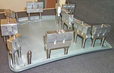
- Good fixture design is important. The fixture has two main purposes: align the parts under the horn and support directly under the weld area. Supporting under the weld also includes reflecting the ultrasonic energy back to the weld plane. In order to reflect the ultrasonic vibrations back to the weld plane, a fixture machined from metal typically is used. Materials such as aluminum and stainless steel are good choices. An aluminum fixture can be plated or anodized to prevent (black) aluminum oxide from transferring to the plastic part.
- In some instances, cast polyurethane may be used to create a fixture. This material tends to be compliant and not cause any surface marking to the plastic part, but can break down from heat or moderate- to high-production use. Replacements may be more frequent.
Three critical factors that determine the success of an ultrasonic welding assembly are frequency, thermoplastic type and metal type. Failure to accurately assess any of these aspects in light of the specific application can lead to an ineffective weld.
Determining the correct frequency for the application
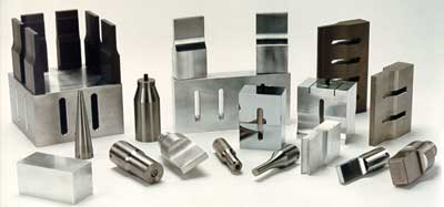
Building a horn for ultrasonic welding is not totally unlike building tooling for injection molding machinery. Different tonnage injection molding machines require different sizes of molds. Different ultrasonic frequencies allow the production of different sizes of horns for welding different sizes of parts. Manufacturers of ultrasonic equipment make ultrasonic welders that operate at different frequencies to provide machinery that best meets the requirements of a given application. The most common frequencies for ultrasonic welders are 15, 20, 30 and 40kHz, but some manufactures have selected to produce machines at frequencies that are slightly different, such as 19, 28 and 35kHz.
One key element for the ultrasonic tooling manufacturer is to design the horn to resonate at the frequency generated by the machine, or it will not function. There are horn size limitations for different frequencies. It also is necessary to produce horns that separate any secondary frequencies from the primary frequency, so the machine knows the correct frequency on which to run.
The process of determining the correct frequency to use for a given application often is one of trial and error, but there are some excellent guidelines that can point one toward the best selection. The 20kHz frequency is the most common frequency found in the industry for plastic welding. The 20kHz frequency can weld a broad range of plastic part sizes and perform other applications like staking, swaging, cutting, fabric sealing and insertion that can be accomplished with the ultrasonic process. At 20kHz, parts have been welded using a single tool up to 9x12" and as tiny as 1/8" in diameter. For insertion of metal into plastic components, 20kHz equipment is the most common frequency used as the transducers (converters) are very rugged at the 20kHz frequency range and can withstand the impact of a vibrating horn contacting a metal insert. Additionally at 20kHz, equipment manufacturers make high wattage equipment with the capability of installing metal components up to ½" in diameter.
When staking a plastic stud or spot welding two plastic pieces together, 40kHz equipment may be the most prevalent frequency used with these types of applications. However, it is not uncommon to see 20, 30 and 35kHz used for ultrasonic staking and spot welding. 40kHz also is the most common frequency used for welding small parts, parts with electronic components enclosed, parts with appendages attached that might be damaged during the ultrasonic process and applications that just require smaller sized equipment. The approximate diameter of a 20kHz transducer is three inches, while a 40kHz transducer is two inches. Additionally, the length of a 20kHz ultrasonic ½ wave horn is close to five inches and the length of a 40kHz ultrasonic ½ wave horn is close to two-and-a-half inches. As expected, the shorter the horn length, the higher the frequency. This smaller size allows the 40kHz equipment to be used in closer proximity, making the use of 40kHz equipment common in machines having space constraints and multiple ultrasonic transducer/horn assemblies. 30kHz provided a bridge between 20 and 40kHz that allows more power and amplitude to be delivered than 40kHz, but still less amplitude and power than 20kHz.
Although the 20kHz frequency can weld parts up to 9x12" with a single horn, this is atypical for 20kHz equipment. The horn design that can be manufactured to operate at 20kHz is limited for welding a part this size. Also, welding a large part of this size using 20kHz usually is limited to ABS or Styrene materials. Different plastic material to be welded at this size generally will lead one to choose 15kHz equipment. Large horns can be produced to run efficiently at the 15kHz frequency, which allows for welding of larger parts, parts with more irregular geometries, parts that have a substantial difference from the horn contact surface to the joint interface and more difficult-to-weld materials.
The material melt flow at the joint can be influenced by the vibratory frequency and how energy transfers through the material at a given frequency. This transfer of energy can be different for varying part geometries, distance to the weld joint, plastic material used and amplitude needed to weld. Even with all of the above guidelines to help point the way, it often comes down to the following questions:
- Can a horn be built for the part size to be assembled?
Tuning a horn to the resonant frequency is not always an easy process due to the size and shape of the plastic part. - What frequency machine does the customer have available to weld the part?
Type of thermoplastic to be welded affects frequency
The higher the frequency, i.e. 40kHz, the more the energy is dissipated or attenuated in the material, resulting in a reduction of distance the mechanical vibrations will travel in the material. The lower the frequency, the further the energy travels through the part before it is attenuated. In some difficult-to-weld materials at high frequencies, the mechanical vibrations created by the ultrasonic energy can be completely dissipated near the top surface where the horn contacts, so the distance from the horn contact surface to the weld joint will impact the frequency needed to weld. Some plastic materials transfer the energy more readily than other materials, so it becomes a combination of the type of material and the distance to the weld joint to determine if a specific frequency will work for a given application.
As a general rule, the chemical composition of the material to be welded will greatly influence the distance the ultrasonic energy will travel in the material. The amorphous-type plastic materials usually allow the mechanical energy to travel further down the material from the horn contact surface to the weld joint. Amorphous materials are plastics with generic names like polystyrene, ABS (acrylontrile butadiene styrene), acrylic and polycarbonate. Crystalline resin-type plastic materials usually attenuate or restrict the mechanical vibrations, reducing the distance the energy travels from the horn contact surface to the weld joint. Crystalline materials are plastics with generic names like Nylon – polyamide, polyethylene, polyester and polypropylene.
The distance to the weld joint from the horn contact is defined as near field and far field. For years, a ¼" or less has been defined as a near field weld condition and more than a ¼" of distance has been defined as a far field weld condition. Because the ultrasonic energy is attenuated in plastics to a greater degree at higher frequencies than at lower frequencies, the distance to the weld joint from the horn contact surface will determine the feasibility of using a particular frequency. For example, if the part is ABS and the distance to the weld joint is three inches, this condition is known as a far field weld. Since the frequency determines the distance the energy travels in the material, the most logical choice would be to consider a lower frequency, 15 or 20kHz. It is questionable as to whether a higher frequency 40kHz welder could transmit the energy through the ABS material over a three inch distance and create a good weld. However, because the material is ABS and readily transmits the ultrasonic energy, for a small part one might consider the use of a higher 30 or 40kHz frequency if the weld joint is closer to a near field weld condition. But, let’s say the material is a crystalline polypropylene PP material and the distance to the weld joint is ¼". At first glance, it might appear that all frequencies could be considered since the weld joint is a near field condition. However, with PP crystalline material the energy is absorbed so rapidly by the material it also is questionable that a good weld could be achieved using the higher 40kHz frequency.
As one might imagine, the combination of material, part design and joint design is exponential, but hopefully the guidelines of material type and the distance from the horn contact surface to the weld joint help to direct one towards a frequency choice that is suitable for the material and the part design. In most ultrasonic welding applications, it is a combination of the part size, part geometry, material used and distance from the horn contact to the weld joint that determines the best frequency.
Metal type affects the assembly process
Most ultrasonic horns are manufactured using specific grades of aluminum and titanium; however, D2 steel and CPM steel also are used for some specialty applications. As a first step to determining a horn metal to be used, one first must analyze how much amplitude is required for the application. Based upon the plastic material and the type of application, the range of required amplitudes needed is broad. Of course, horn costs, wear, size of the horn and quantities of parts to be assembled all must be considered when selecting a metal type for the assembly process.
Most 20kHz ultrasonic welders produce approximately 20 microns or .0008 of movement at the face of the transducer when activated by the ultrasonic power supply. In other words, the face of the transducer is expanding and contracting 20,000 times per second for a total displacement of 20 microns. There are not many applications for plastic assembly that can use such a small amount of motion to effectively melt material. The two other components used with the transducer to increase the amplitude level to a more workable level are the booster and the horn. The booster is simply a tuned horn with a nodal mount point that allows the transducer, booster and horn assembly to be held for the purpose of delivering the ultrasonic energy to the part. The boosters are rated by the amount of gain they increase – the 20 micron motion that is produced at the face of the transducer. The typical booster gains are 1:1, 1.5: 1, 2:1 and 2.5:1. These booster gains are used to put the transducer, booster and horn assembly at the needed amplitude for a given application.
The ultrasonic horn is designed to fit the part being welded, the stud being staked, the textile being cut or welded and the insert being installed. However, another very important element to the horn design is building gain into the horn, so the transducer, booster and horn assembly have sufficient amplitude to perform the application at hand. Building gain into the horn adds stress to the tool and plays a role in determining what horn material should be used.
As previously stated, the amplitude required to perform a specific function varies tremendously with the application. Fortunately, most applications have a range of amplitudes that will work for the assembly process.
The reason that amplitude reference information is important for the ultrasonic tool maker is it provides the guidelines for the type and style of horn that needs to be built to achieve the amplitude levels required for the application. Build a horn with insufficient gain and the application will not work. Put too much gain in the horn and it adds stress to the tool, reducing the life of the horn. Remember, a horn is expanding and contracting at a rapid rate, and the further the horn is expanded and contracted the greater the potential for the horn to fatigue.
What horn material should be used? Because it is important to reach high amplitude levels for some applications, it is absolutely critical in these situations to use titanium material instead of aluminum for the ultrasonic horn. The fatigue strength of titanium is approximately 2.3 times that of aluminum. At very high levels of amplitude, the aluminum horn might not last very long. However, at lower levels of amplitude, the aluminum horn can last for a very long period of time. An aluminum horn will cost substantially less than a titanium horn, because the cost of titanium material compared to aluminum material is significant. The increased machining time required to produce a titanium horn versus an aluminum horn also increases cost to the end user. There are excellent benefits for using aluminum horns where the application allows; however, there are times one simply cannot use aluminum and titanium is the appropriate material due to the application requirements.
D2 steel is very prone to fatiguing at ultrasonic frequencies where high gain levels are required for the application. Fortunately, the application where D2 tool steel most commonly is used for ultrasonic assembly is installing metal components into plastic parts, and this application does not require high amplitude. Since ultrasonic metal insertion is a high-wear application, D2 steel proves to be the material of choice for high-production insertion jobs. This is not to say that titanium will not work for insertion applications, but one will see improved tool wear when using D2 steel horns for metal insertion installations. For some high-wear applications where the plastic material is particularly abrasive to the horn face, CPM steel has been used. Although the CPM steel can run at an amplitude level exceeding aluminum, it also has a higher resistance to acoustical energy transfer than aluminum or titanium. Therefore, CPM is not acoustically as efficient as titanium or aluminum.
It’s always a matter of trade off regarding which metal material to use for manufacturing horns. Aluminum is the most acoustically efficient, followed by titanium and then steel, but aluminum has the drawback of increased fatigue failure and reduced wear resistance.


