Optimizing Ultrasonic Welding Results
by Jeffrey Frantz
Branson Ultrasonics Corp.
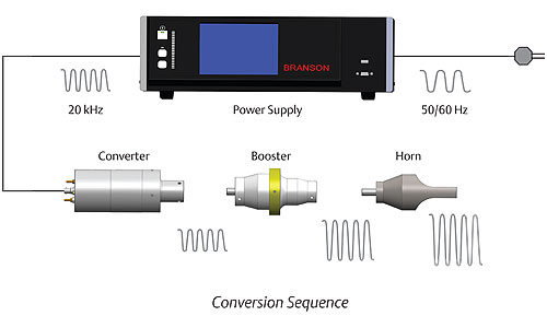
Figure 1 shows how the power supply, converter, booster and horn function together to create mechanical vibration.
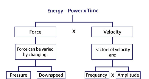
Figure 2 - The main parameters in an ultrasonic weld can be derived through the fundamental equation shown here.
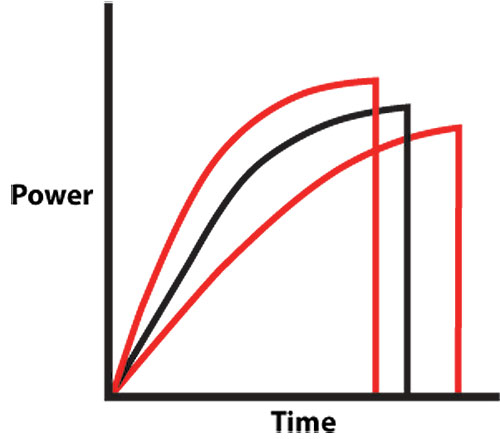
Figure 3 demonstrates a typical power graph that illustrates these two weld modes.
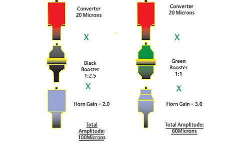
Figure 4 shows a 1:1 booster and a 1:2 gain booster. The horn design is determined by the horn it is to contact. It should be designed to contact over the area to be welded. Based on size, frequency and material limitations, gain may or may not be incorporated. When these three components are attached, they create what is known as stack amplitude.
Ultrasonic welding is a technology that has been used for decades to assemble plastic components. There are many benefits of this technology. It allows for plastic parts to be assembled without consumables. This not only eliminates the cost of the consumable (such as screws or rivets), but in the case of adhesives and solvents, eliminates the set-up or cure time, which dramatically improves throughput. It is an extremely fast technology as most welds occur in less than a second. It easily can be integrated into semi- or fully automated systems, and it also is a very cost-competitive process. With all of these benefits, it is easy to understand why ultrasonic welding often is the first choice for plastic joining needs.
Lets begin with a brief description of the process. The ultrasonic vibrations are created by a series of components – power supply, converter, booster, horn and actuator – to deliver mechanical vibration and force to the parts. This generates heat at the interface of the parts to be joined, melting the plastic and creating a strong bond.
Figure 1 shows how the power supply, converter, booster and horn function together to create mechanical vibration. The power supply takes standard electrical line voltage and converts it to an operating frequency (in this illustration, 20kHz). Power supply frequencies are set, but are available between 15 – 70kHz. The most common frequencies are 20, 30 and 40kHz. This electrical energy is sent through an RF cable to the converter. The converter utilizes piezoelectric ceramics to convert the electrical energy to mechanical vibrations at the operating frequency of the power supply. This mechanical vibration either is increased or decreased based on the configuration of the booster and horn. The proper mechanical vibration, known as amplitude, typically is determined by an applications engineer and based on the materials being welded.
Mechanical vibrations are delivered to the parts to be welded. The parts also are put under a mechanical load, primarily through a pneumatic actuator. Under this load, the mechanical vibrations are transmitted to the interface between the parts. In most cases, there is a triangular-shaped bead, known as an energy director, designed into this interface. This creates a point for the vibration to be focused, resulting in intermolecular and surface friction. This friction creates heat and a subsequent melt.
The main parameters in an ultrasonic weld can be derived through the fundamental equation shown in Figure 2.
Amplitude is the dominate parameter and has a significantly greater impact on the weld than the other parameters. Amplitude is the peak-to-peak movement of the horn. This motion, coupled with force being generated by pressure and downspeed, creates a condition where the amplitude produces waves of energy that move through the part contacted by the horn. These mechanical waves of energy create stress at the joint interface in the form of intermolecular and surface friction. This creates heat that propagates from the point of contact between the parts to the entire joint area. Once the ultrasonic energy is stopped, the joint cools and solidifies to form a weld. All of this takes place, in most cases, in less than 500 milliseconds.
The weld process can be broken down into some very basic sections. It is important to distinguish them and make sure they are individually controlled. First is the approach to the part. This is the distance between the home position and the part. Next is the point of contact to the part. This is known as trigger. The weld duration is next, followed by hold.
Lets start with the approach to the part. This distance most often is predicated by having enough space to load and unload the part in manual operations and minimal distances in automation. This typically is controlled through the downspeed setting, which regulates through a flow meter on the output side of the air cylinder. It is important to note that this setting not only controls the velocity of the horn to the part, but also the buildup of force during the weld.
There are many ways to control the ultrasonic weld. This most often is done through a controller that comes with the welder. In its most basic form, the weld is controlled by time. Time generally is set in milliseconds. The next level of control is energy. This is done through a watt meter that calculates the watts per second, known as joules. The illustration in Figure 3 demonstrates a typical power graph that illustrates these two weld modes. As seen in the energy mode, the weld time will vary slightly due to minor variations in part-to-part tolerances. Energy mode is used in some applications where there are multi-cavity combinations being welded.
The original energy setting was based on the center power profile. The area under the curve is the weld energy. The surrounding graphs show power curves that have a slightly different power draw. The weld time fluctuates to meet the weld energy set in the controller.
In more sophisticated units, a linear encoder is attached to the actuator. In most cases, it has a resolution of 0.0001", which allows for many different functions to be utilized and controlled. In the approach to the part, the point (in distance) that a pre-trigger will initiate the ultrasonics can be precisely set. A pre-trigger often is used in shear joint, staking and insertion applications to turn the ultrasonics on prior to the horn contacting the part. This prevents the parts from being pressed together. In an actuator without distance capability, the pre-trigger would be turned on as soon as the horn leaves its home position, which can create excessive noise, horn failures and inconsistent weld results.
The linear encoder also is used to provide two additional modes of weld control: Collapse and Absolute. Collapse is a controlled measurement between the point of contact and the part. For instance, if a part has an energy director joint design that is 0.015" high, the Collapse could be set to that exact amount. The welder would reset the linear encoder readings once the horn contacts the part, and then moves the 0.015" set in Collapse and then turns off the ultrasonics. Absolute is a control mode that sets the distance the actuator will travel. It is used when the part requirement is to maintain an overall height dimension.
There also is a Peak Power capability which will turn off ultrasonics when a peak power point is reached. This mode is not often used, but can be a benefit in plunge welding of textiles. Due to the openness of the materials, they go through a rapid transition once molten. This results in a quick spike in power consumption. Peak Power mode prevents what is known as "blow though", where the weld flash melts through the surrounding area.
Often overlooked in a weld sequence is the trigger point. This is the point in the process where the actuator has made contact with the part, the cycle is initiated and the processing mentioned above takes place. In most weld systems, a mechanical trigger is used. This is adequate, but for more precise control a load cell that measures force provides a higher level of control.
Lets now look at the set up of the welder. As mentioned earlier, amplitude is the most important parameter for successful welding. The amplitude is created by the gain ratios of the stack, which encompasses the converter, booster and horn. The converter has a fixed ratio determined by the manufacturer. For this example, we will work in 20kHz which has an output of 20microns. The booster and horn gains are determined individually by the mass ratio of their input to output masses. Figure 4 shows a 1:1 booster and a 1:2 gain booster. The horn design is determined by the horn it is to contact. It should be designed to contact over the area to be welded. Based on size, frequency and material limitations, gain may or may not be incorporated. When these three components are attached, they create what is known as stack amplitude.
It is imperative to have the proper stack amplitude to match the material being welded. Each material has a range of amplitude for ideal weld results. For instance, Polycarbonate has an amplitude range of 60-100microns. It will weld with amplitudes outside of this range, but should be well within the range for optimum results. The supplier of the horn should provide horn gain information so the user can calculate which booster is best for the material.
Once the stack components have been selected, properly torqued and installed in the actuator, the next setting is weld pressure. In most cases, a setting between 30 and 50psi is adequate. Naturally, lower pressures should be used for smaller thinner walled parts, with high pressures used for larger parts with thicker walls. The next setting is downspeed or velocity. This determines the rates of descent of the horn to the part, but ultimately it determines the rate of force build up during the weld. Most weld setups utilize a setting between 1.5 -2.5 in./sec.
The next parameter to set is weld mode and duration. With all of the weld modes available, where do you start? Many of us utilize our past experiences to select a weld mode that worked previously. This may or may not be successful. Ideally, you should always start in the time mode. The other modes do have benefits, but also can mask some potential issues or restrict the process from behaving naturally. The best practice is to use the time mode and let the parts tell you what is best for them. Let me explain.
You will need to run some trials and use your judgment in refining the weld settings until you get an acceptable part. Once you have achieved an acceptable part that passes all of your test criteria, you should set up a DOE (Design of Experiments) to determine the optimum settings for amplitude, pressure and downspeed. This will lead to your ideal settings. From there you can begin work on selecting the optimum weld mode. To do this, you will need to weld a grouping of parts (quantity to be determined, but usually no less than 50) and the tools to collect weld data. The more cavity combinations incorporated in this analysis, the more accurate the findings. It is imperative that you weld and label the parts to correspond with the weld data. At a minimum, the weld data should include energy, peak power, collapse and absolute.
The next step is to inspect and test the parts. Look them over visually and then put them through whatever tests are applicable. There most likely will be a few of these parts that fall outside of acceptable ranges. Compare those parts with the weld data. There will no doubt be some variation in the data. It may be in energy or collapse or absolute, but there will be variation. Compare the data between the good and bad parts, and let the data indicate the mode with the most consistency. Change the weld mode and run the experiment again. Results will improve.
Once the weld mode has been optimized, you then can move to the next step, which is amplitude control. You already have determined the stack amplitude with the converter, booster and horn, but the amplitude also can be changed electronically during the weld. This is known as amplitude profiling. The principle behind this technique is to use a high level of amplitude in the early stages of the weld to bring the material to its molten or softened state. Once heated, it no longer requires that high level of amplitude. To increase control of the melt, decrease the amplitude setting at some point midway through the cycle. In many cases, a decrease from 100 percent to 70-50 percent will provide another level of weld consistency. Another DOE on the amplitude profile settings is recommended.
It seems like this process is quite extensive and may take a good deal of time to complete, but in reality it is time well spent in the early stages of product and process development. Time spent here will pay huge dividends when full scale production begins. Throughput will be higher and the time spent tweaking the process on the floor will be minimized.