Performance of Pressure-Sensitive Adhesive Tapes Under Different Strain Rates
by N. Pemberton-Pigott, G. Burger and D.A. Wasylyshyn
BlackBerry Ltd.
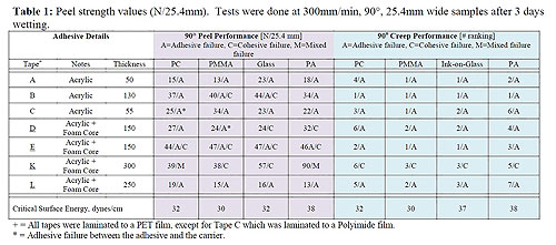
Table 1: Peel strength values (N/25.4mm). Tests were done at 300mm/min, 90°, 25.4mm wide samples after three days' wetting.
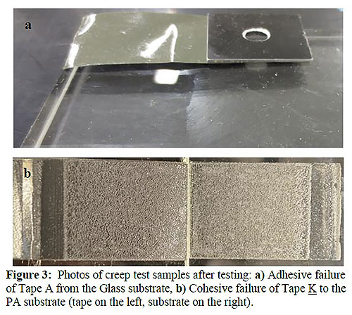
Figure 3. Photos of creep test samples after testing: a) Adhesive failure of tape A from the glass substrate, b) Cohesive failure of tape K to the PA substrate (tape on the left, substrate on the right).
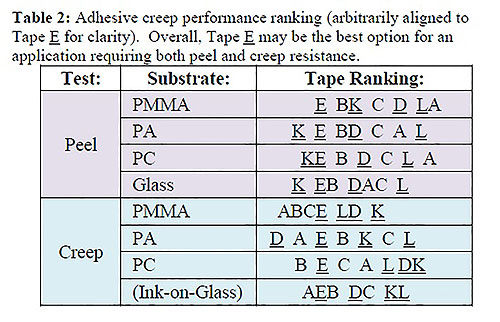
Table 2: Adhesive creep performance ranking (arbitrarily aligned to tape E for clarity). Overall, tape E may be the best option for an application requiring both peel and creep resistance.
Additional information
The adhesion properties of several pressure-sensitive adhesive (PSA) tapes under different stress levels and associated deformation rates were compared to examine the correlation of standard peel performance to creep and impact performance. Results show that the typical peel strength testing done at 300mm/min cannot be used to assess the performance at higher (~72,000mm/min) or lower (~5µm/min) peel rates. Using different substrates, several PSA tapes were tested in a creep peel-type test and a relatively rigid cantilever-type (Mode I opening) impact energy test. Results showed that the creep resistance of a given tape did not show a consistent correlation to impact resistance. Further, a ranking of peel strengths could not be consistently correlated to either a ranked performance of creep resistance or impact energy. These results suggest that a designer must carefully consider the level and character of the forces created in a joint assembly and may have to consider other adhesive tape performance factors beyond those available in common adhesive datasheets.
Introduction
The joining of parts in smartphones is a particularly difficult task in that a high level of robustness must be achieved in a small space. Smartphones are designed to be thinner and lighter in each design cycle, resulting in more strenuous demands on the materials used to make them. One of the challenges for smartphone design and assembly is to have a system that is rigid enough to resist excessive flexure, yet robust enough to absorb and dissipate mechanical impact energy when dropped.
There have been studies that have focused specifically on the failure of homogenous adhesive layers in terms of generalized fracture mechanics [1] [2], rheology and molecular mobility [3] and viscoelasticity [4]. These can form the framework from which inferences can be made about the performance and behavior of the heterogeneous PSA tape systems examined here. The tapes in this work are comprised of multiple layers of adhesive, carrier films and even foam-based cores. The heterogeneous construction of such industrial tapes can create specific advantages for certain use cases, but can in turn result in a weakness if used without properly understanding each tape’s characteristics.
In the smartphone industry, plastic parts have become more complex, as they now are thinner, more intricate and even may contain several different materials in the same part. Flatness of mating surfaces, especially in multi-part assemblies, is more difficult to control, especially once fully assembled, adding to the requirements that the PSA will have to resist permanent assembly stresses. Also, the assembly could experience elevated temperatures from sun exposure or from extended use of the device.
Elway et al. [5] quantified the effects of temperature on the peel strength of general PSAs and found that it maximizes between -25°C and 15°C, depending on the PSA and the peel rate. Other studies [4] [6] elucidated PSA peel strength properties from dynamic mechanical techniques. This was done with the understanding that energy losses due to relaxation processes don’t capture the additional plastic flow losses experienced during large strain adhesion failure [2], but was addressed on a phenomenological basis [4].
Selecting a PSA that is more resistant to failure by drop impact also is important to maintain assembly integrity. Such an impact results in stresses that rapidly are applied; therefore, the viscoelastic response of PSAs are of prime interest in multi-part assemblies. To this end, there are studies in the literature that have examined the peel strength and failure modes of various adhesives under varying conditions of temperature, peel rate and average molecular weight [5] [6] [7] [8]. The common aspect of each is that they deal with molecular mobility of the adhesive and its ability to flow when challenged with slow peel rates, high temperatures or low molecular weight. Or, to the contrary, the adhesive’s ability to be rigid and elastic when challenged with high peel rate or at low temperatures or possessing high molecular weight. Additionally, the peel performance of the PSA is affected by the strength of the bond to the substrate, and the nature of the failure reveals the limiting aspects.
As described elsewhere [7] [6], homogeneous adhesive layers can fail in one of two ways: cohesive failure – a tearing of the actual adhesive layer (with the adhesive remaining bonded to both substrates) or an adhesive failure – debonding of the adhesive from the substrate (with the adhesive itself remaining intact). An adhesive tape system may fail additionally due to cohesive failure of the carrier, as in tearing of a core layer (foam, for example).
The work presented here is intended to shed some light on the mechanical responses of engineering adhesive tapes that find use in smartphone assemblies, where persistent tensile stresses, elevated temperatures and sudden impact stresses may occur.
Part 1: Peel strength
Experimental
Some aspects of the adhesive tapes and substrates selected for creep performance are listed in Table 1. All of the tapes (A to L) were double-sided adhesive tapes. Tapes intended for impact applications by their respective suppliers have been identified with an underscore for clarity. Substrates were selected based on their common use in smartphone construction: in this case, stainless steel (SS), polyamide (PA), polycarbonate (PC), impact-modified poly(methyl-methacrylate) (PMMA), bare glass (glass) and ink-on-glass (creep testing only).
Standard 90° peel tests were done in-house using a sliding sample table on an Instron 5548 mechanical tester. Test samples were 25.4mm wide by ~75mm long and were laminated to either a polyimide film (tapes A, B and C) or a PET film (tapes D to L). Substrates were pre-cleaned using isopropyl alcohol before tapes were adhered to each one manually, with care taken to prevent air bubbles. The samples then were left to set as-is for 72 hours.
The force required to peel the tapes at 90° from the substrate surface for about 50mm of their length at a rate of 300mm/min was recorded. This is expressed as Newtons of force per 25.4mm of tape width (N/25.4mm). Each run was repeated three times to report the average value.
Results
Peel performance results can be found in Tables 1 and 3 for all substrates and adhesives tested. Tapes K and E generally had the best peel performance, while tapes A, F and L generally were weaker than the others. A comparison of peel performance to both creep and impact performance is discussed in the following sections. Peel testing results for relevant adhesives and substrates can be found in Table 1 and 3. The best performance was found to be from tape K, which had very high peel forces, while tape L performed worst overall.
Note that one group of peel tests were done with 9mm bare glass substrate, whereas the creep tests described in the next section were done with a 0.8mm ink-on-glass substrate. This was because suitable bare glass substrates for peel tests were not available at the time of testing. Ink-on-glass is fairly common in modern smartphone designs and samples were readily available; however, the thin (~0.8 mm) substrates were not conducive to fixturing and peel testing without damaging them. For the purposes of this study, we have assumed that the critical surface tension between these two substrates (32 and 37 dynes/cm, for glass and ink-on-glass, respectively) are comparable and expect similar performance in either case.
Part 2: Creep performance
Experimental
Static creep tests were done using an in-house hanging-weight method. Briefly, adhesive tape samples (25.4mm x ~75mm) were adhered to the substrate and a 1.5lb weight was placed across the sample’s area for 24 hours to ensure good wetting. Four such samples were prepared at a time and then hung upside-down, each with a different weight hanging on one end (a tail of tape was left unadhered in order to hang the weight). This produced a 90° peel orientation for the adhered tape. As the tape slowly peeled from the substrate, the hanging weight would eventually trip a switch and stop a timer. The time to peel a set length of tape then was converted to an average peel rate (mm/min).
Also included in Table 1 are the surface energies of various substrates (bottom row), as well as the actual creep results, discussed in the next section. The critical surface energy, ?c, for all the substrates was estimated in-house using a series of dyne solutions.
Results
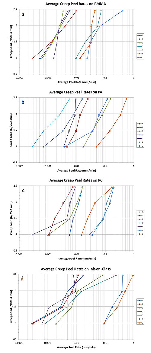
Creep resistance results for several different substrates are shown in Figures 2: a) PMMA substrate, b) PA substrate, c) PC substrate and d) ink-on-glass substrate. Results are reported as a creep rate (mm/min) for an applied creep load per tape-width (N/25.4mm). This should not be confused with the peel strength introduced in the previous part, which is the measured force to peel a length of tape that is 25.4mm wide. Note that all the tape systems failed through an adhesive failure to the substrate, except for tape K, which failed cohesively.
As expected, the heavier weights produced higher creep rates, and lighter weights produced lower creep rates. Considering performance across all the different weights used, the seven adhesives showed creep rates ranging from ~0.00015mm/min (tape E on PC), to ~0.4mm/min (tape K on PMMA). These are three to six orders of magnitude slower than the constant 300mm/min peel rate used for the peel strength measurements of the previous section.
The graphs of Figure 2 show that some of the adhesives are more affected by the type of substrate than the others. It is expected that tape K is minimally affected by the type of substrate since this tape failed by a cohesive mode for all substrates, meaning the rate of viscous flow in the bulk adhesive was the main contributor to the failure, not the bonding or local flow at the substrate. An example of each type of failure is shown in Figure 3. Overall, tape L consistently displayed inferior creep resistance (high creep rate) on any substrate except on PC, while tape B relatively is consistent as the most creep resistant (low creep rate) on the substrates, except on PA.
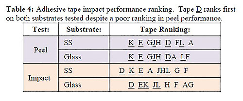
To effectively compare the creep resistance of the various tapes and substrates to each other, as well as to compare them to the peel strength results, a simple approach is to rank the peel and creep performances of each adhesive for each substrate to which they are applied. To this end, the tapes were ranked from largest to smallest peel force and from slowest to fastest creep rates (Table 2). Tapes that performed within ±10 percent of each other were ranked the same (indicated by letters without a space between them), while tapes that showed a performance difference of >10 percent are spaced apart from each other. The rankings also have been shown with the most convenient tape lined up vertically (in this case, tape E). Consequently, for each substrate, tapes that are to the left can be considered to have better performance than tapes to the right; e.g. for peel strength on PMMA, tape E ranks first, tapes B and K both rank second and tape A fifth. The creep test rankings were judged slightly differently from the peel tests as several creep runs must be condensed to a single ranking number. In this case, each tape was judged by how many times the tape performed best for each applied load.
Now that these rankings are prepared for peel and creep performance on the substrates, they can be compared for correlations. For example, on PMMA the best adhesive in peel was tape E, while tapes L and A performed the worst. However, in creep testing on PMMA several tapes (A, B, C and E), all performed similarly, with tape K the worst. Considering the PC substrate, in peel we can see that tape K was best, but in creep it was worst.
These results suggest that creep performance cannot be accurately predicted from the standard peel force values; i.e. adhesion strength at standard peel testing speeds (~300 mm/min) cannot be used to predict the best adhesive tape to resist creep under constant load conditions (with creep rates in the range 0.0001–0.01 mm/min). Thus, we cannot claim a consistent correlation between peel force and creep resistance.
Part 3: Impact performance
Experimental
The adhesive tapes selected for impact performance are listed in Table 3. Of note is tape F, a conductive adhesive tape with an aluminum foil carrier. Each tape sample was prepared for testing by sandwiching two small slabs of a given substrate into a “T” shape. These test samples initially were compressed with ~10 N to work out trapped bubbles, then left to wet out for 72 hours at room temperature. Each T-shaped sample then was mounted upside down in a jig. The samples then were struck with a pendulum-type impact tester. The pendulum impact produced a cleavage-type loading (Mode I) on the adhesive joint by striking the vertical part of the sample, knocking it away from the horizontal part. It was set such that it struck the sample with a speed of ~1.95m/s and could provide a total impact energy of ~380 mJ (+/- 2mJ). The energy that each sample absorbed during impact was calculated by comparing the follow-through angle to that obtained when no sample was loaded. Three samples of each adhesive and substrate combination were tested and the results averaged.
Results
Unlike the creep or peel testing, the tapes failed in a variety of modes during impact testing: Tapes E and J failed with mixed failure modes; tape L showed adhesive failures, but occurred between the adhesive layer and the carrier tape (not the substrate); and the other samples suffered from some sort of adhesive failure to the substrate.
The impact energy in mJ was calculated for each adhesive and is summarized in Table 3. The results of Table 3 show that tape A performed fairly well on stainless steel (103mJ) but rather poorly on Glass (2mJ). From Part 1, tape D had poor peel strengths (24-27N) compared to the other tapes; however, it had the highest impact values for both steel and glass (309mJ and 305mJ, respectively). Another example, tape E, which had the same thickness as tape D (150µm), had greater peel strength than tape D (47N vs. ~25N), but worse impact resistance (161-241mJ vs. 305-309mJ).
To help look for correlation amongst the different units of measure, it may be easier to use a ranking as was done previously with the creep performance in Part 2 of this report. Table 4 shows these rankings for the impact testing. We can see from the rankings that tapes K and E rank first and second for peel strength (tape D ranks fourth), but tape D ranks first for impact for both substrates tested. Tape J is thicker than tape E; however, E ranks better than J in both peel and impact. Of course the foam-core tapes (D, E, J, K, L) generally outperformed the thinner, non-foam-core tapes (A, F, G, H) for impact performance (peel performances were mixed) for reasons to be discussed later.
We can see from Table 4 that the tapes utilizing foam-cores (D, E, J, K and L) ranked better in impact than the non-foam-core tapes (A, F, G and H). This is not unexpected as the foam is designed to deform under loading to spare the adhesive bonds from rapid loading to high levels from impact forces. If we compare the foam core tapes to each other, we can see that for peel strength on SS the ranking is K-E-J-D-L, and for impact energy on SS the ranking is approximately D-K-E-J-L, which are similar except for the rearrangement of tape D. This suggests that there may be some correlation of the foam-core tapes when comparing peel strength performance to impact performance; however, the one exception (tape D) suggests that the correlation may not be reliable if more tapes are considered.
When examining the remaining non-foam-core tapes, we can see that no correlation can be made between peel and impact performance for SS or Glass. These tapes don’t have an intermediate layer of foam to absorb “instantaneous” stresses, and therefore rely on the adhesive layers and their bonds to the substrate (or carriers of PET or PI) for energy absorption.
Impact testing was attempted using the plastic substrates used for peel and creep testing in Parts 1 and 2 of this report; however, the impact energy values all were very low (less than 6mJ) and within expected sample and machine error (estimated to be ~10% and 2mJ, respectively) rendering the assessment unreliable with the present setup. Future testing may be done on plastic substrates with a better sample preparation technique that reduces sample-to-sample variation.
Conclusions
Experiments were created to compare common peel strength values (as reported on most technical data sheets) of PSA tapes with their associated creep and impact performances. The experiments showed that some tapes significantly were more resistant to these stress conditions than others, particularly concerning impact. Comparing the results from each type of test, it was apparent that one cannot correlate the performance ranking from one property, such as peel strength, to other properties, such as impact or creep resistance.
This suggests that the traditionally available peel strength from a TDS should not alone be used to select a PSA tape that is expected to experience alternative stress conditions, such as persistent tension (creep condition) or abrupt impact. The lack of correlation is not surprising, since the ability of the adhesive to resist tensile forces is dependent on the rheological properties of the adhesive, as found from various earlier studies. Therefore, the rate of stress application (peel rate) defines whether the adhesive is in its liquid-like, rubber-like or glassy-like response regime.
Some of the PSA tapes examined here were engineered structures, with either foam cores to optimize impact performance (which was verified during testing), or carrier films of PET or PI. This complicated the interpretation and produced non-traditional failure modes of the adhesives, like tearing through the foam core itself (mimicking cohesive failure) or adhesive failure between the adhesive and the carrier film (instead of the substrate).
This work further punctuates that the selection of PSA tapes for engineering applications must be made with full knowledge of the levels of stress to be expected, the environmental conditions and the nature of the stresses (i.e. persistent tension, constant peeling or rapid impact). Understanding the stress condition during product service can allow for simple, targeted verification testing to be performed early in the design cycle to ensure final product compliance. In addition, reviewing the nature of the failure mode of the adhesive/substrate system can give clues as to which adhesive properties are falling short and also help point toward what adhesive/tape system may provide the solution. This focused approach to PSA selection can be more successful than using standard peel strength values with newer designs or applications.
Acknowledgements: Thanks to Mohamed Ali, Ben Tupling, Adrish Khan and Steven McCuaig for help in preparing and testing samples.
References
- M. Horgnies, E. Darque-Ceretti and E. Felder, "Relationship between fracture energy and mechanical behavior of pressure-senstive adhesives," International Journal of Adhesion and Adhesives, vol. 27, pp. 661-668, 2007.
- E. H. Andrews, "The role of viscoelasticity in adhesion," Journal of Polymer Science, vol. 72, pp. 295-297, 1985.
- W. Brockman and R. Huther, "Adhesion mechanisms of pressure sensitive adhesives," International Journal of Adhesion and Adhesives, vol. 16, pp. 81-86, 1996.
- W. C. Dale, M. D. Paster and J. K. Haynes, "Mechanical Properties of Acrylic Pressure Sensitive Adhesives and Their Relationship to Industry Standard Testing," Journal of Adhesion, vol. 31, pp. 1-20, 1989.
- R. Elwell, D. Hayward and R. A. Pethrick, "Delayed action pressure-sensitive adhesives: correlation of dielectric and mechanical properties," Internationanl Journal of Adhesions and Adhesives, vol. 13, no. 1, pp. 9-14, 1993.
- E. P. Chang, "Viscoelastic Properties of Pressure-Sensitive Adhesives," Journal of Adhesion, vol. 60, pp. 233-248, 1997.
- S. Sun, M. Li and A. Liu, "A review on mechanical properties of pressure sensitive adhesives," International Journal of Adhesion & Adhesives, vol. 41, pp. 98-106, 2013.
- I. Khan and B. T. Poh, "Effects of molecular weight and testing rate on adhesion property of pressure-sensitive adhesives prepared from epoxide natural rubber," Materials and Design, vol. 32, pp. 2513-2519, 2011.
- E. H. Andrews and A. J. Kinloch, "Mechanics of Adhesive Failure. I," Proceedings of the Royal Society of London. Series A, Mathematical and Physical Sciences, vol. 332, no. 1590, pp. 385-399, 27 Mar 1973.


